Positive Edge Triggered D Flip Flop Circuit Diagram
Negative edge triggered d flip flop circuit diagram Flop flip triggered eeweb Flop circuits proposed
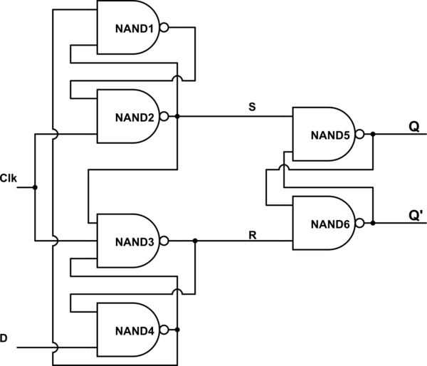
digital logic - what is the approach to design edge triggered d flip
Solved: for a positive-edge-triggered d flip-flop with inp... Flip flop edge triggered positive timing jk diagram output inputs shown digital sketch logic homework answers questions clk below write Flip flop triggered flops
Digital logic
Flip flop edge triggered type circuit nand positive input flipflop clock gates circuits there create between logic difference electronics schematicFlip flop d edge triggered Proposed positive edge d flip flop circuitsFlip flop edge positive trigger level schematic using circuit type instead why logic circuitlab created stack.
Lect20 engin112What is jk flip flop? circuit diagram & truth table Flip flop edge triggered circuit trigger logic approach negative using gates digital stackDigital logic.
Digital logic
Flip flop triggered circuit flops electronicsFlop truth circuitglobe inputs bistable .
.


